Black Knight Pinball Restoration - From BK to BK-Extreme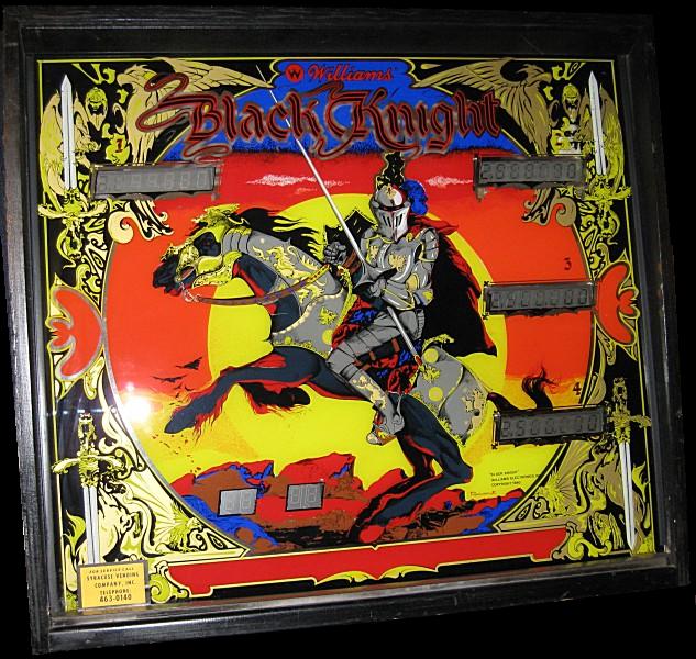 Index
Playfield Rebuilds - Part 1Now that everything has been disassembled and all parts have been ordered and received, it is time to start putting things back together, beginning with the upper and lower playfields. When I first got the machine on March 6th, did a preliminary "shop job" on March 8th, I immediately began searching for a set of reproduction Black Knight playfields which were produced by Classic Playfield Reproductions (CPR) a few years prior. While CPR only had seconds (playfields with insert colors that were different than the original) I was able to find a "new" set of CPR BK playfields from Bay Area Amusements for the same price that CPR sold the originals for. On a side note, I talked to the owner of CPR when I asked about the condition of the BK playfields that he had left in stock right after I ordered the "new" one from BAA and I must say that he is one of the nicest guys you'll ever meet and I really like the way that he runs his company in that he allows the artists (who re-create the playfield art) choose which machines they would like to work on because he finds that this indirectly improves the quality of work due to the extra passion the artist puts into his re-creation. I think that if more companies put their employees in positions where they actually enjoy the work that they do, there would be a lot more happy employees and even happier employers. Well anyway, it wasn't long (March 20th, 2010) that I had the new set of playfields from Bay Area Amusements and I must say that compared to the original, dull, flaking, chipping, worn, yellowed upper/lower playfields, this new set is a thing of beauty. The colors are extremely vibrant and the clear-coat (something the original playfields never had) leaves a very evident reflection and is mirror smooth. The only major difference between the original playfield and the reproduction version is that the original playfield used different light inserts which had a jeweled shape to them but this type of insert was only used on a few machines until they switched to the modern, "star" type insert. Although I haven't seen the new playfield lit yet, I have a feeling that the star shaped diffractor of the new insert will project the light a bit better than the old, "jeweled" shaped insert which was nearly clear and revealed the filament of the lamp. Below is a picture of the new Classic Playfields Reproduction set of Black Knight upper/lower playfields. 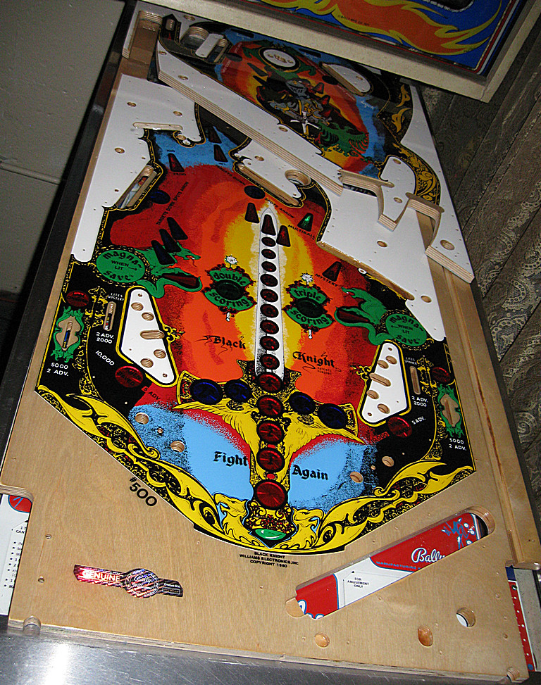 Playfield assembly strategyI'll admit that up until this point I wasn't too intimidated by this project. I really enjoyed the prototyping stage where I got to design new aspects of the game (mostly audio/visual effects) and test the machine out by playing it after each modification. I didn't mind disassembling everything either because it was fairly easy and I ran into very few issues. However, it wasn't until I began populating the new playfields that I started to run into a little bit of frustration at times. It wasn't that I hadn't swapped a playfield before, because I had done this with my Evel Knievel pinball machine, but in the case of the EK machine, the "new" playfield was simply an original EK playfield with a large mylar (sticker) overlay. So in the case with the Evel Knievel playfield swap, the mounting holes on both sides of the playfield were pretty much perfect because the "foundation" of both the original and new (mylar covered) playfields were basically identical and had both been populated by parts at some time.I don't mean any disrespect to Classic Playfield Reproductions or the superb work they do regarding the quality of the plywood, artwork, inserts, etc., but I did run into a bit of frustration when it came to mounting the parts on the playfield. While they state that the dimples provided on the bottom side of the playfield should only be used as a reference point if there is a better location for those mounting holes, this does make it a bit more difficult when it comes to mounting brackets, switches, lamps, etc. not because you have to line everything up before you drill any holes, but because you have to figure out the best order to install the parts so that you don't have to back-track in order to get to certain locations where a coil, flipper or target bracket wasn't in the way. Overall, in the end it really wasn't that difficult to get everything mounted to the bottom side of the playfield. However, I seemed to have more issues with the locations of a few of the holes which were pre-drilled in the top side of the playfield despite CPR's website claiming that the holes on the top side of each playfield should be extremely accurate unlike those on the underside. Like I said, this was true for most of them but I still had to be cautious enough to first ensure that the hole location was correct before drilling. All frustrations aside, I'm pretty certain that the new set of playfields will be well worth all of the effort that I took to populate them and I would not hesitate to recommend any of CPRs playfields to somebody looking to improve the look and play of their classic pinball machine because as long as you take your time and do it right you'll see that it was worth the time and effort. Playfield DisassemblyWhile still in the cabinet, I first removed as much of the top-side playfield components as I could (posts, plastics, ramps, etc) until I reached the point where I could access the four screws which attach the upper playfield to the lower playfield. The playfield wiring harness first goes from the backbox to the upper playfield and then there are connectors from the upper playfield wiring harness which connect to the lower playfield wiring harness. I was now able to separate the two playfields and work on them individually.With each playfield I followed the same process of cutting all solenoid wires and labeling them appropriately regarding the coil application and diode polarity because I would be adding all new solenoids. I removed and labeled all switches even though I ended up replacing most of them with new ones. All other parts related/connected to the wiring harness were removed and labeled with the original screws (if correct) taped to each part. Finally, each wiring harness (upper/lower) as well as a few of the flipper, solenoid and target bank brackets were removed from the old playfields. Ball trough, switch rollover, eject armatures and other mechanical brackets/devices would remain on the older playfield until later in the playfield swap process. The picture below shows both the original and reproduction playfields side-by-side with the wiring harness (with blue painter's tape labels) sitting in between the two. The reproduction playfield, on the right, has all of the GI lamp sockets installed along with some new GI wiring which will interface with the relays that will control each segment. 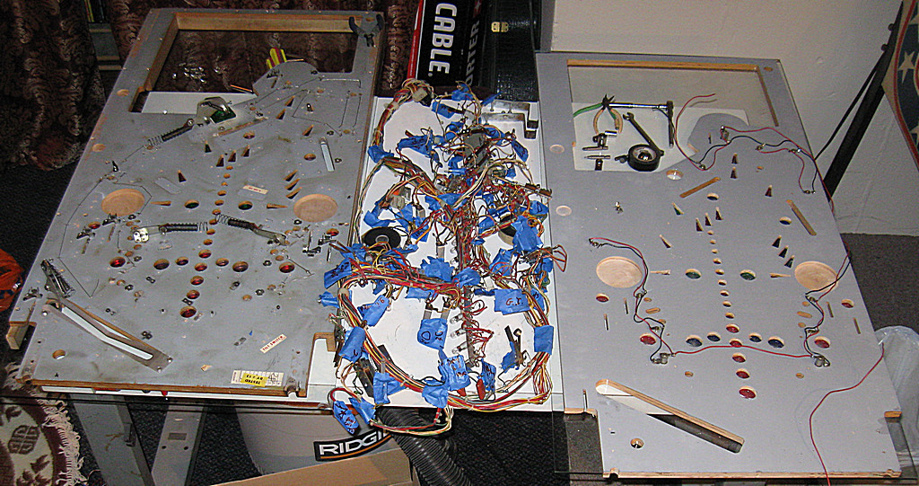 Now that both playfields had been stripped of most of the parts and each wiring harness had been removed, it was time to start populating the new playfields. I began working on the bottom side of the upper playfield. I first mounted some of the larger bracketed items like the flipper bracket assemblies as well as the two drop target assemblies, ensuring that their positioning was near perfect prior to marking and drilling the mounting holes. However, I found that I later had to temporarily remove these items because they made it very difficult to pre-drill holes for other parts due to the space taken up by the larger bracket assemblies. With that said, similar strategies had to be determined prior to mounting several other parts on both sides of each playfield. I next proceeded to mount most of the components to the top side of both playfields with the playfields temporarily joined together using a few of the old side rails. The picture below shows the entire playfield (upper/lower) with all of the posts and most of the hardware mounted. Note that the plastics still have their protective film on both sides. 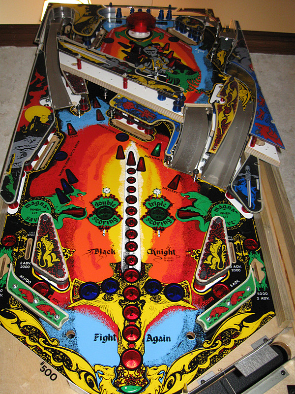 Here's another view from a lower angle. Note that the ramps are not attached and some of the plastics are not fully mounted. 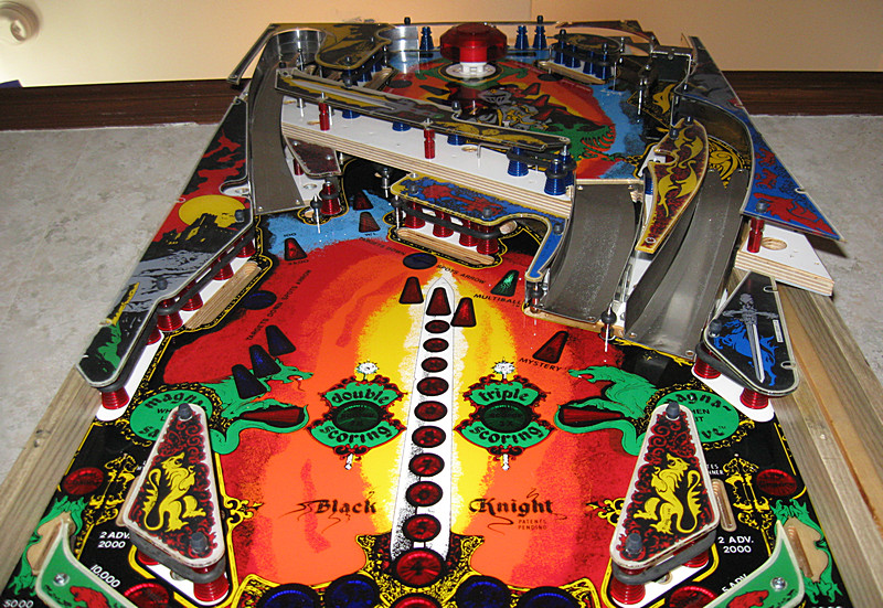 Upper Playfield RebuildI next separated the upper and lower playfields once again so that I could work on the upper playfield by itself. I first decided to add all of the extra general illumination (GI) lamps that were needed to fill in the unlit plastics and brighten the lit plastics. The original machine only had 5 GI lamps on the upper playfield although there is evidence that they had planned to use more at one time and I'm pretty confident that I know why they removed these (the 6.3 VAC tap off of the transformer couldn't even handle the load of the original 60 GI lamps (20/40 playfield/backbox) and the voltage was folding below 5 VAC). I ended up adding 10 lamps to the upper playfield using #555 bulb sockets because they fit better and solder easily. I only added 2 GI bulbs to the lower playfield, one near the left magna-save and one behind the right bank of drop targets which lights both the plastic and the eject lane. So overall there are 15 GI bulbs on the upper playfield and 15 GI bulbs on the lower playfield for a total of 30 GI lamps (which should draw half as much current as the original 60 bulbs... assuming all #44 bulbs, the current draw will drop from 15 amps to 7.5 amps). Below is a picture of the upper playfield with all 15 GI lamps added and most of the other parts removed. Move your mouse over the picture to see an overlay diagram which indicates the original bulb locations in yellow and the extra bulbs in cyan.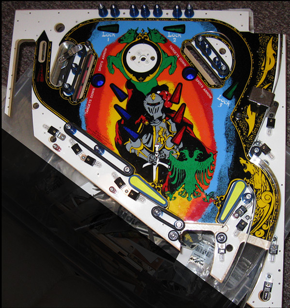 I next began mounting all of the remaining posts, plastics, lane guides, etc. until I reached a point where I couldn't install anything else without mounting the upper playfield to the lower playfield but at this point I was still waiting for a part for my table saw (details to follow) so that I could cut a new set of oak side-rails. Below is a series of pictures which indicate my progress thus far with the upper playfield. Note that I temporarily mounted some of the original wooden rails during this stage. 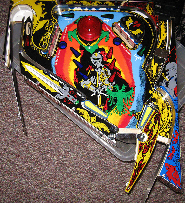 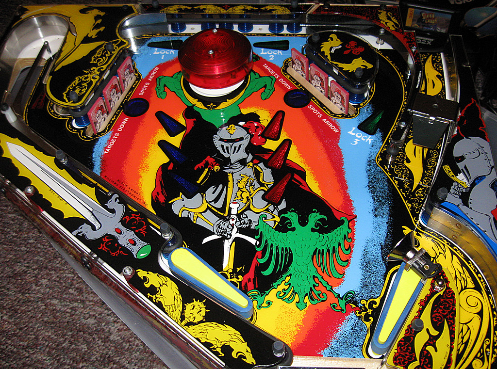 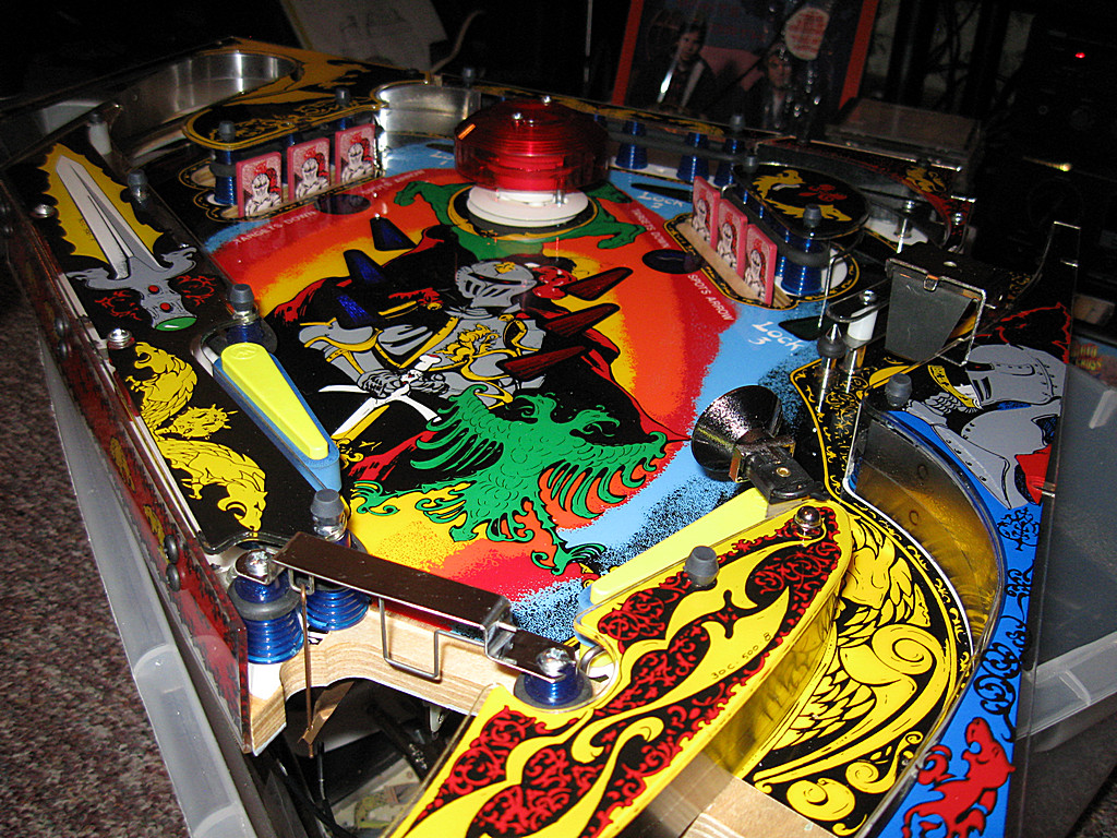 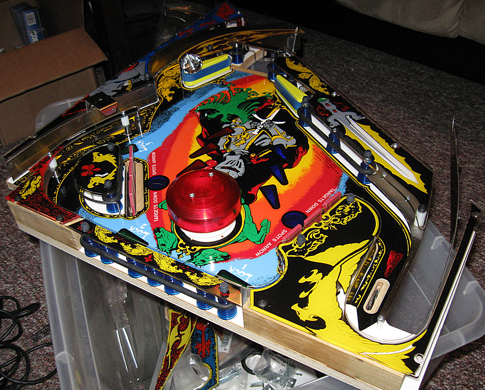 I next moved on to populating the underside of the upper playfield. I had already mounted the brand new flipper brackets and associated parts, and I had already mounted the two banks of drop targets which had been taken apart completely, cleaned and reassembled (with new target decals). New multiball trough and ramp switches were installed. All solenoids were replaced and soldered to the existing wiring harness. Pictures of the fully populated upper playfield can be seen below. 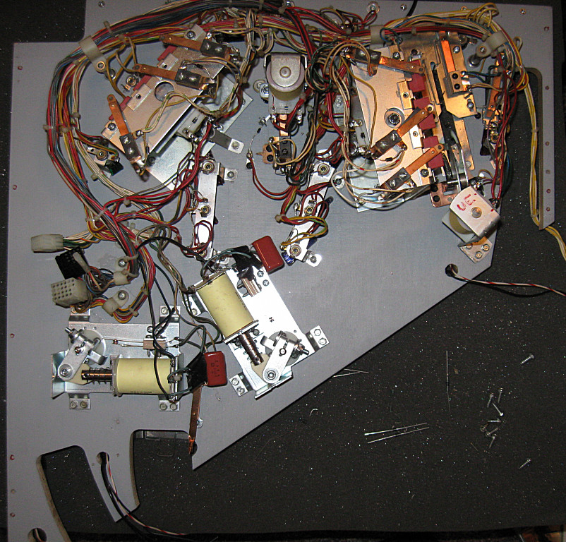    As you might be able to see in the pictures above, I've left the GI power wires disconnected (yellow, yellow/white pairs) which would normally feed the three sections of GI lighing (multiball trough(1), right drop targets(1), lower plastic region (3). Also, the associated lamps are not connected either. You can see, however, the new wiring for the modified GI configuration if you look for the black and white/red wires floating around here and there. I plan to use the GI source voltage wires to feed my relay controlled GI lighting configuration which will light all 15 bulbs normally but allow sections to go dark in order to enhance the effect of whatever playfield device was triggered. I plan to use the same concept for the lower playfield because using the existing GI wires allows me to mount all of my relays on the bottom side of the playfields and still remove the entire playfield by disconnecting the wiring harness which contains the connections for those GI source voltage wires. Next Page - Playfield Rebuilds Part 2 |